You are currently browsing the tag archive for the ‘FischerTechnik’ tag.

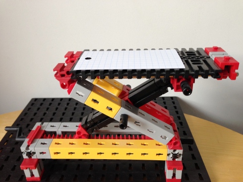
Scissor-lift of FischerTechnik, paint brush, shallow glass box, glif attachment, olloclip lens, iPhone, tripod, LED torch
We have been working on ways to take photographs of insects at home. Here are some of the tools and techniques we have found useful:
Camera
We have been using an iPhone 5 with the OlloClip 4-in-1 macro lens. This gives us a magnification of 15 x – which is better than many hand lenses.
Magnification inevitably results in a shallow depth of field, so achieving a clear focus requires care. The iPhone camera software allows you to lock the focus, if you tap and hold until the square yellow box flashes around your finger. The Olloclip software doesn’t appear to allow this, although it does allow you to set the focus and exposure on separate parts of the image, which is sometimes useful too.
To keep it steady, the camera is held on a tripod with a glif attachment to hold the phone on.
Scissor-lift
C has made a scissor-lift (out of FischerTechnik) to enable us to do fine height adjustments of the subject, relative to the camera. The lift has a threaded rod, and turning a handle moves the platform up and down relative to the camera. This degree of fine control was not possible with our tripod, but the lift ensures it is easy to make frequent small adjustments.
We have a piece of plain paper on top of the platform to give a neutral background.
Glass box
J has built a small glass container, approx. 80 x 50 mm, which stops any live subjects from roaming too far. They can still wander/skitter out of view, but it increases the chances of capturing a photograph. The box is made of 3 mm picture glass, glued together with a silicone glue (RTV). You can often get glass off cuts from a picture framer.
The sides of the box are only 11 mm high (with a glass lid on top of that) which enables us to get sufficiently close with the camera. For some creatures you can take the lid off – but for the more mobile individuals, that is not an option.
The flat sides also mean we can get clear photos from the side – unlike the distortions you get with a petri dish or a plastic container.
Any moving of the insects that is required is done with a fine paint brush.
Lighting
Lighting is also important. Natural light (although not direct sunlight) is sometimes sufficient, since we are using a tripod. When it isn’t, we use an LED torch.
The reason for using LED’s is that (unlike a tungsten bulb) it doesn’t produce much heat, so it doesn’t overheat the creature below.
Examples
Here are some examples of our results so far, of insects found in several Christchurch gardens:
Other subjects
This same general setup is also useful for photographing other subjects, such as the details of plants, rocks, shells etc.
Next
Some ideas we have yet to try include:
- Try some focus-stacking software – this involves taking a series of images, each focusing on a different plane, and then the software stitches them together into a single clear photo.
- Find some way of aligning the camera to the eyepiece of our stereo microscope, that provides 40x magnification.
- Perfect a cooling box which will slowly cool an insect just enough to slow it down for photography, but that will also allow it to subsequently warm up and recover.
- Build a tall narrow (approx. 11mm wide) aquatic observation tank, for photographing more of the small creatures from ponds and aquariums – something like this. And find a suitable lighting method for aquatic subjects.
Do you have any tools/techniques you can recommend?
One of us is 7, so obviously we made a trebuchet. Actually we have made several in the last year or so – the current version goes sufficiently high and far to only be useable outside.
We used FischerTechnik, which allowed us to easily experiment with the design ourselves by adjusting each component.
This website was helpful in detailing what to aim for in the design.
The design features we found useful were:
- The main frame needs to be quite sturdy – we used quite a bit of bracing
- The optimum ratio for the length of the weight arm to the projectile arm is 1:3.75
- The arm needs to be strong but light
- The length of the sling (we used linen thread) should be about the same length as the projectile arm
- The counterweight needs to swing freely
- The mass of the weight should be about 100x the mass of the projectile
- The angle of release (affected by the pin angle) should be about 45o
- There needs to be a smooth surface for the projectile to travel along before it is launched (we used some cardboard to smooth the transition over the base)
- Solid ground underneath helps (e.g. not carpet)

Weight – full of metal screws and weighing about 400 gm, to match our projectile of approx. 4 gm. There is a hinge connecting this weight to the end of the arm so that it swings freely.
It is interesting to adjust various parts and see the effect. For instance,
- small weight + 60o pin = 4.1 m range
- heavier weight + 60o pin = 3.7 m range
- small weight + 30o pin = 8.3 m range
- medium weight + 30o pin = 8.7 m range
The projectile is difficult to see in a video, so we fired it at dusk with LEDs attached to the projectile:
And here is a video:
It would be nice to be able to provide a general description of the physics of how a trebuchet works, but it turns out to be rather more complicated than it initially appears. There is an explanation by Donald Siano here if you really want to get into it.
Physics explanations aside, they are quite satisfying to make and to fire. I expect our next (better, bigger) version will require trips to a park so as to be able to launch projectiles without losing them into the neighbours place.
This was a quick weekend project, inspired by some YouTube videos.

Three small servos, stuck together with double-sided tape, form the body of the bot. Two servos point upwards and the centre one points forwards. Hot-glue connects the galvanised wire legs to the servo horns. The parts are small, so use a small hot-glue gun if you have one. Hot-glue and double-sided tape are strong enough for the bot, but not so strong that the parts can’t be disassembled and re-used.

The robot walks by pushing the middle leg down on one side, then using the servo on the opposite side to swing the body of the robot forwards. The servo on the near side also rotates in the same direction at the same time, so as to be in position for the next step.
To turn the bot, the top servos are rotated in opposite directions during each half cycle.
A standard Arduino is far too big for this bot, however, an Arduino Pro Mini is smaller than the back of the bot (18mm x 33mm). The Pro Mini is a full featured Arduino, but without the USB interface. To program this board you also need an FTDI adapter like the Sparkfun FTDI breakout. There is no connector on the Arduino, but you can just hold the header pins on the FTDI breakout against the holes along the end of the Arduino.
The Arduino Pro Mini I had was the 5V version. Lacking a boost converter to turn the 3.7V battery into 5V, I tried wiring the battery directly to the Arduino and everything worked. The 110mAh battery I used is tiny and fits underneath the bot.
An infra-red LED and infra-red photo-transistor form the obstacle detector. The photo-transistor is wired with its emitter to ground and its collector to Vcc, via a 5.5k resistor. The Arduino measures the voltage across the photo-transistor. There is a fair amount of ambient infra-red light, so the bot measures the voltage on the photo-transistor with the LED turned off, then again with it turned on. If the voltages are much different, it’s time to turn. In a sunlit room, a black paper tube to shield the sides of the photo-transistor will make detection more reliable.
Parts
- 3 small 3-6v servos
- Arduino Pro Mini
- 110mAh lithium-ion battery (and charger)
- Sparkfun FTDI Breakout or Adafruit FTDI Friend
- Infra-red LED
- Infra-red phototransistor, e.g. TOPS-050
- 5.5k resistor
- hookup wire
- heatshrink tubing
- Hot glue gun
- Double-sided tape
- rubber bands
- 1.25mm galvanised wire for the legs
If you live in New Zealand MindKits and Nicegear are good sources for this stuff.
The Arduino sketch can be downloaded from https://bitbucket.org/johnmccombs/bot8_3_servo_walking_robot/get/1d8d6c769bb2.zip or cloned from the bitbucket repo https://bitbucket.org/johnmccombs/bot8_3_servo_walking_robot


